How To Use Conceptual Models for Better UX and UI Design

When you’re designing for a friendly user experience and user interface, you start with a concept. You have an idea of how it should work in the real world. You just need to communicate it to the rest of the design team.
Welcome to the world of what we call Conceptual Models. In this article, we will explain what Conceptual Models are and how to use them.
Design interactive prototypes in UXPin and make your concept palpable and easy to grasp. UXPin is an all-around prototyping tools that covers every part of UX process, from conceptualization till design handoff. Check it out. Try UXPin for free.
What Is a Conceptual Model?
A conceptual model is a representation of a system. It shows how people, places, and things interact. They show the real-world features and interactions of your design idea.
In other words, a conceptual model is an abstraction of a piece of the real world or a design you plan to bring into the real world.
Conceptual Models That You Already Know
Google Maps
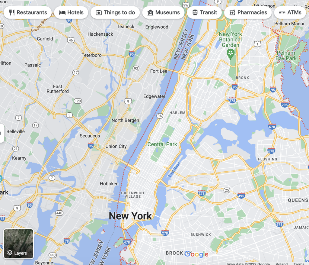
When you pull up Google maps on your mobile phone or another device, you will see a representation of the roads, bridges, intersections, restaurants, fueling stations, retail stores, and points of interest.
Let’s say you want to visit Carnegie Hall in New York City.
You enter “Carnegie Hall” into the search engine. It brings up a map of the area around 7th Avenue and West 57th Street in New York, New York, USA.
You’ll see that the 57th Street Subway Station is across the street from Carnegie Hall, so you can just take the train to get there..
You’ll also see that there are restaurants, diners, and hotels nearby in case you get hungry during your visit or want to stay overnight.
These facilities appear on the map as sketches of buildings with labeled markers showing their location. Cartographers at Google maps that show you the concept of the area of New York near Carnegie Hall.
A Planetarium
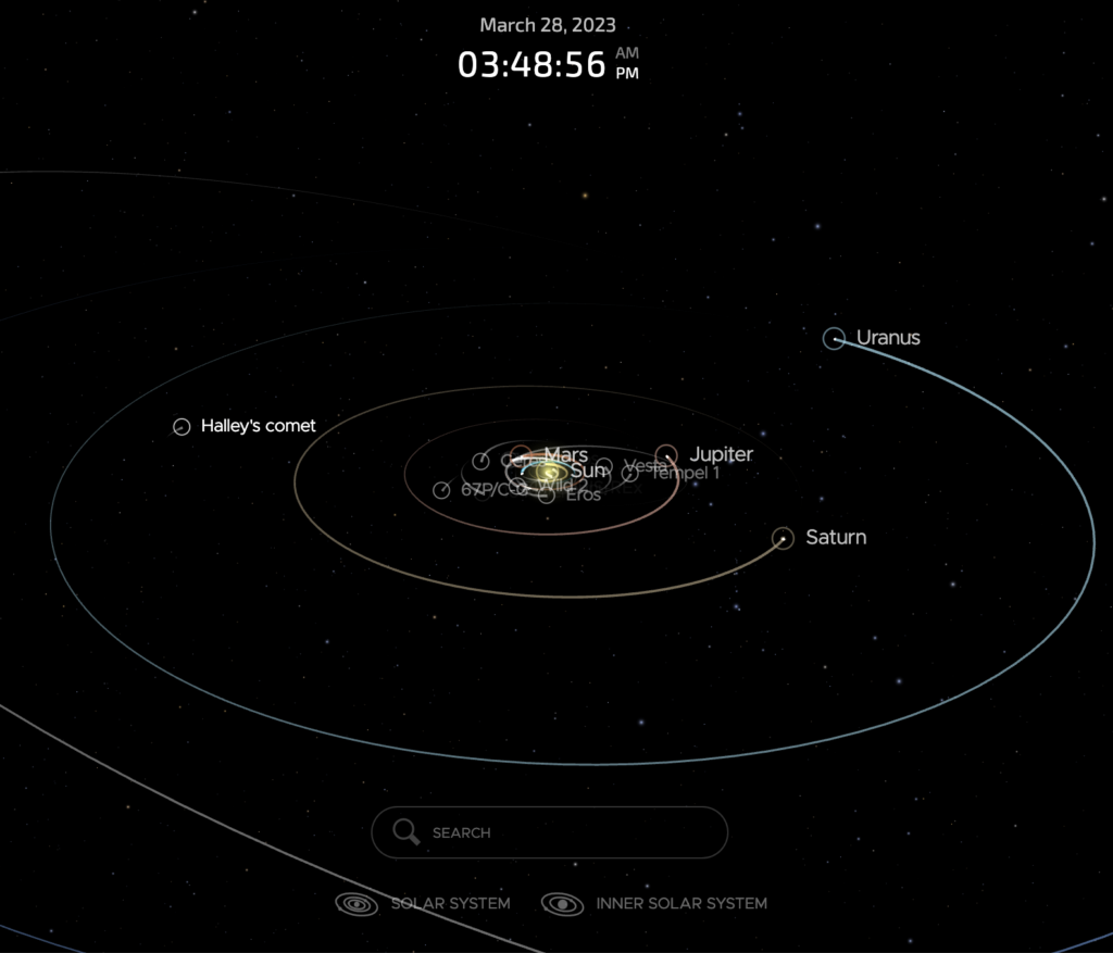
Take an orbital model of the solar system. It has spheres that represent the Sun and planets. They’re mounted on arms that hold the “planets” at a distance from the “Sun” that’s proportionate to the distances of the real-world planets.
Within a complex system of gears, wheels, cogs, and sprockets, the spheres revolve around the “sun” and rotate just as the real-world planets.
It’s not the solar system, but it shows you how the planets move.
A Flowchart
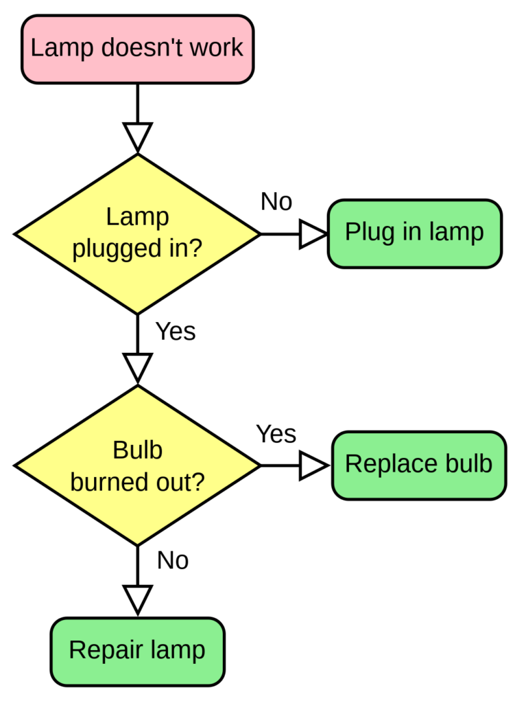
A flowchart represents processes. You have:
- Ovals signify the beginning and end of the process.
- Rectangles represent steps of the process.
- Diamonds symbolize a decision.
- The text describes the steps and actions.
- Document icons that could mean “print invoice” or “review sales report.”
- Input, output, merge, and other symbols.
- Arrows show the direction of the process flow.
As you can see that conceptual modeling can take many forms.
And they’re not media dependent. That is, you can create them with a sophisticated design program or draw them on a piece of paper.
Conceptual Model Entities
Conceptual modeling entities are the symbols of real-world objects in a system. Let’s take Google Maps again as an example.
You’ll see that it has lines to represent the streets. Two parallel lines represent West 57th Street to show that it’s a 2-way street.
7th Avenue is a single line because it’s a one-way street. It has arrows to show the direction of traffic flow in the real world.
We’ll talk more about entity interactions later.
In the case of the planetarium, we have spheres that represent the sun and planets. The entity that signifies the sun is at the center of the model. It’s usually a yellow-colored sphere that’s larger than the others.
Closest to the “sun,’ you have the entity (a small sphere) that depicts Mercury. The second-largest entity is farther out and symbolizes Jupiter. And so on with the other planets.
In a flowchart, entities appear as icons with text descriptions.
Entity Classes and Instances
Entity classes are the universals. Instances are particulars.
For example:
- Class – Street
- W 57th St
- 7th Ave
- Broadway
- Class – Restaurant
- Chai Thai Kitchen
- Brooklyn Diner
- P.J. Carney’s Pub
- Class – Hotel
- Park Central Hotel
- The Wellington
- Courtyard by Marriott New York
Conceptual Model Relationships
Conceptual model relationships depict an interaction between entities.
It’s like forming a sentence where you have a subject, a verb, and an object. The relationship is the verb. The entities are the subject and object.
For example:
- Karen Smith (entity) checks in (relationship) at Park Central Hotel (entity).
- The box office (entity) sells (relationship) tickets (entity).
Conceptual Model Constraints
Constraints govern entity relationships within a conceptual model. You may recall that there are entity classes and instances. One instance might interact with a whole class. A class may interact with other classes. Or an instance may interact with only one other instance. A class might not interact with any other classes. Some possible constraints are:
- One and only one. This indicates that only one entity of this type is in the system. For example, an orchestra has one conductor.
- Zero or one. You can think of this as a yes/no or an on/off constraint. For example, one customer attending a performance at Carnegie hall has a season pass. Another does not. The entity that we call “season pass” has a constraint value of 1 in its relationship with the first customer. With the second customer, the value is 0.
- More than one. You express this as a minimum and maximum value. An orchestra might need a minimum of 4 violinists. A full-sized symphony orchestra has no more than 34. The constraint value for the entity labeled “Violinist” is 4 to 34 in relation to an entity named “Orchestra.”
- One or more. Here you have to have at least 1. An entity named “Musicians” must have a value of at least 1 to have a relationship with the entity “Musical Performance.”
- Zero or more. This says that it’s possible to have none of this kind of entity and that you can one or more. You might not sell any tickets to a performance. But if the performance hall has 3,671 seats, that’s the maximum value.
Suppose you’re creating a conceptual model for a database for Carnegie Hall. Some of the constraints might look like this:
- People
- Musicians
- Conductors – 1 and only 1
- Violinists – 4 to 34
- Violas – 4 to 12
- Customers
- Season pass holders – 0 to 1,000
- Robert Johnson – 1 and only 1
- Musicians
- Performances
- Event on 5 April 2021
- Sold tickets – 0 to 3,671
- Unsold tickets – 0 to 3,671
- Event on 5 April 2021
And relationship constraints might be:
- Conductors (1 and only 1) to violinists (4 to 34).
- Customers (0 to infinity) to seats (0 to 3,671).
- Robert Johnson (1 and only 1) to season passes (0 or 1).
Putting It Together
You have an idea for a system, and you know what you want it to do in the real world. Now you need to communicate the idea to your teammates. So far, you’ve looked at the parts of a conceptual model.
- Entities – the people, places, and things.
- Relationships – how the entities interact with one another.
- Constraints – the number of entities interacting.
You want to keep it simple. Start with the drawing tools inside UXPin. That way, you can quickly share your idea with the entire design team, clients, investors, and other stakeholders.
The great thing about UXPin is that you won’t need to export your design file to another program when you move from concept modeling to prototyping.
Use the box tool from the editor to add entities to your model. Add text inside of a box to label the entity.
You can include the constraints inside the box or add text outside.
Use lines to show entity relationships. If the interaction only goes one direction, draw an arrow. Add text to describe the relationship.
Suppose you’re making a conceptual model for a system to sell tickets to an event at Carnegie Hall. It might look something like this.
You may have noticed that the entity “People” has no constraint value. It’s omitted to keep things simple. It could easily carry a value of “0 to infinity” or the current earth’s population. You don’t have to show every detail, as long as everyone concerned understands.
Tips For Success
- Establish the goal. Who is the product for? What does it do for them?
- Brainstorm. Create a simple model. Get input from team members. Add details as needed.
- Evaluate. Do you understand the concept? Do team members understand the concept? Does the model communicate it clearly?
- Iterate. You may need several versions before finding the best way to convey the idea.
Final Thoughts
When you kick off a UX/UI design project, conceptual modeling can be valuable to any design team.
- Establishes entities. It defines the people, places, and things represented within the model.
- Defines project scope. How big is it ? How much time will it take to build it?
- A springboard for creating more concrete models.
- Keeps everyone on the same page. Some team members might not work with code. But everyone needs to understand what’s going on.
For UX and UI designers, a conceptual model is a first step in communicating what you want the system to do for the user.
Keep your model simple. You don’t have to include every possible entity, relationship, or constraint value. Covering every detail can lead to a lot of time waste.
When you create your conceptual model in UXPin, your teammates and stakeholders have instant access. That lets them input their ideas and give feedback. And there’s no need to export to another design tool when you’re ready to move to the next stage of the project. Take your design to another level. Try UXPin for free.
